
| WWT Shows | CLICK TO: Join and Support Internet Horology Club 185™ | IHC185™ Forums |

|
• Check Out Our... • • TWO Book Offer! • |
Welcome Aboard IHC185™  Internet Horology Club 185 IHC185™ Discussion Site Main Page Horological Discussions, Questions and Answers Pocket Watch Discussions Help finding US Patent 833489 (Edward Staehli - 1906 Stem-Wind and Set)
Horological Discussions, Questions and Answers Pocket Watch Discussions Go | New Topic | Find-Or-Search | Notify | Tools | Reply to Post |
| IHC Member 1736 |
I can find the Gruen Patent for the safety pinion... but can not find the patent stamped on the pillar plate of the watch I have posted in the European section. This is a Suisse made Gruen with a US Patent number stamped under the dial on the pillar plate. The watch has an interesting mix of Swiss and American attributes throughout the movement. | ||
|
| IHC Life Member |
Not my "First Rodeo", this is 833489 In these older PTO files the words are not always easily available, but the patent is pretty obvious. 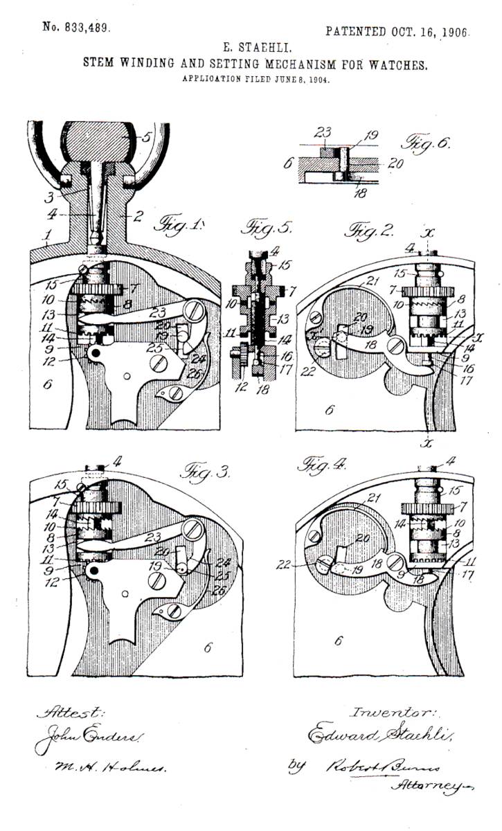 | |||
|
| IHC Member 1291 |
US Patent 833489; Stem winding and setting mechanism for watches. US 833489 A Images(1) Patent Drawing Description (OCR text may contain errors) No. 833,489. PATENTED OCT. 16, 1906- E. STAEHLI. STEM WINDING. AND SETTING MECHANISM FOR WATCHES. APPLICATION FILED JUNE 8. 1904. llllllllllllllflll Tqsmmf Iii-f non-s runs. m: 4 mum. mum-4010M. I)v c. ' sition. the same with the mechanism in position for UNITED STATES PATENT o EIoE. EDWARD STAEHLI. OF 856cc, 'rnLrnols. srzm wmpme And ssh-me. msc umlu sm so? war or-12's. and State of Illinois, have invented a certain new and useful Improvement in Stem Winding and Setting Mechanism for Watches, of which the following is a specification. This invention relates to that class of stem winding and setting mechanism for watches in which an axial outward adjustment of the watch-crown effects an inward shift of a clutch wheel or member into operative engagement with a pinion of the hand-setting mechanism and an axial inward adjustment of said crown to its normal position effects an outward shift of said clutch-wheel into operative engagement with the pinion of the watch-winding mechanism; an the present improvement has for its object to provide a simple and efficient structural formation and combination of parts in the intermediate mechanism between the winding-stem and the clutch-wheel of the mechanism, whereby an easy certain, and effective operation is insure and which is equally adapted to closed and open face watches, as well as to watches which vary in the relative proportions of their parts, all as will hereinafter more fully appear. In the accompanying drawings, illustrative of the present-invention, Figure 1 is an enlarged front. view of my improved stem winding and setting mechanism for watches with the mechanism in position for winding the watch. Fig. 2 is an enlarged rear view thereof with the mechanism in a similar position- Fig. 3 is an enlarged front view of setting the hands. Fig. 4 is an enlarged rear view hereof with the mechanism in a similar position. Fig. 5 is a detail longitudinal section at line a: :c, Fig. 2. Fig. 6 is a detailed transverse section at line as 2:, Fig.2 Similar numerals of reference indicate like parts in the several views. Referring to the drawings, 1 represents the watch-case, having a tubular pendant 2, in which the set-sleeve 3 and the male stem 4 of the whirling-crown 5 are arranged, as position of the present shifting mechanism, with a transverse orifice to receive the winding- specification of Letter! Patent Applied for Aug. 8,1904. Serial s 211.626. - Patented Oct. 16, 1906. * pinion 7 of the mechanism and hold the same in positions with a secondary transverse orifice connecting with the orifice aforesaid and adapted to receive and permit axial adjustment of the clutch member 01' wheel 8 and with-a cross-piece or bridge 9 at the lower end of the second orifice aforesaid to form an abutment for t e inner end of of the teeth 10, adapted for operative engagement with a like set of ratchet-teeth on the adjacent under side of the-winding-pinion 7 of the winding mechanism, and at its lower end such clutch member is formed with a circular set of gear-teeth 11, adapted for operative engagement with the pinion 12 of the hand-setting mechanism. Such clutch member is adapted to have limited independent axial adjustment upon the tubular winding stem hereinafter described, in order that said clutch member may be moved from one to the other of the above described engagements. 1.3 is a peripheral recess the clutch member 8 and intermediate of its length for operative engagement with an arm of the secondary lever of the shifting mechanism hereinafter described. 14 is a tubular winding-stem having a square or like non-circular lower shank portion in operative engagement with a corresponding -formed bore of the clutch member 8 aforesaid. Said winding-stem is also" provided with an upper enlarged head 15, recessed centrally to form a non-circular orifice for operative engagement with the non-circular lower end of the male stem 4 of the winding-crown 5 in a manner to permit of limited axial adjustment between the parts, as usual in the present type of stem winding and setting watches. 161s a push-rod extending-axially through the tubular bore of the winding-stem 14. The- 0 against the upper end of said rod has bearing under side of the male stem4 aforesaid, and its lower end is preferably provided with an enlarged head or enlargement 1.7 for operative engagement by the primary lever of the shifting mechanism hereinafter described. 18 s the primary lever of the present shifting mechanism, pivoted to the inner plate 6," as shown. The inner arm of said lever is of an outwardly-curved form and is arranged to I against' the inner end of the push-rod 16 'al ei:esair l ,"while the outer arm of said lever is'al so of outwardly-curved form and carries near its free end a lateral pin or stud 19, ,the assemblage and removal of the parts. 23'is the secondary lever of the shift in mechanism, having a short inwardly-curved arm, and pivoted to the. main plate 6, as shown, The main arm of said lever is substantially straight, with its free end in operative engagement with the peripheral recess 13 of the clutch member 8, while the other arm is in angular relation to said main arm and is formed with an inclined inner cam-face 24, ending in a straight transverse end bearing face 25, providing an extended guide fort. the lateral pin at an angle thereto concentric, with the. pivot-axis of the primary lever 18. The arrangement is such that. as the pin 19 moves downward against the inner inclined cam-face 24 it will impart a corresponding movement to the secondary lever 23 until the straight transverse end bearing-face 25 is reached, when the pin will move along the same without imparting any movement to the secondary lever 23 and without any liability to disengagement o f the parts due to an excessive downward movement of the pin 19. By such construction the present shifting mechanism is adapted to a wide ran e of watch-movements in that it provides or a wide difference in the adjustment of the winding-"stems of the different movements. 26 is a spring engaging the short inwardly- I curved arm of the secondary lever 23, with a normal tendency to move said lever in the direction which brings the clutch member 8 in operative engagement with the pinion 7 of the winding mechanism. 'Such spring has lever primary 18, in order that said spring 21 will effect a shifting of the clutch member 8 to a hand-setting position, as more fully set forth in the operation of the mechanism. "In operation as allows with the winding-crown .5 in the normal position shown a in fig. 1" its stem is in the inner position shown in Figs; 1 and 5 to longitudinally depress the push rod 16 and, through the primary and secondary levers 18 and 23-, maintain the .clutch member in its upper position and in operative engagement with the pinion of the winding mechanism. With an outward movement of the winding-crown 5 and its stem in the usual manner the holding stress of the stem 5 against the push: Rod 16 is released, and 'said' rod follows the stem 4 in its outward movement under the stress of the spring 21 and primary lever 18, and with such lever moving under the stress of said spring the lateral pin 19 moves against the inner-inclined cam face 24 of the secondary lever 23 to impart movement to the main arm of said secondary lever in an inward direction and through the operative connection of said arm with the clutch member 8 the said clutch member is moved inwardly to release the prior operative engagement thereof with the pinion 7 of the Winding mechanism and to operative engage its gear-teeth 11 with the pinion 12 of the hand setting mechanism. The lateral pin 19 next passes onto the straight transverse end bearing-face 25 to positively hold the secondary 4 lever 23 without imparting movement there to. With the completion of the hand-setting operation the winding-crown 5 is pushed back to its normal position, thus shifting the lateral pin 19 :from the straight transverse end bearing-face, 25 and releasing the secondary lever 23, and a reverse operation of the parts to that last described takes place and the clutch member 8.is returned to its normal engagement with the pinion 7 of the Winding mechanism. Having thus fully described my said invention, what I claim as new, and desire to secure by Letters Patent, is A stem winding and setting mechanism for watches comprising a primary lever carrying a lateral pin and a secondary lever having an arm engaging the clutch member, and a short inward lever acting angular arm formed with an inclined inner cam face with which the lateral pin carried by the said primary lever engages forward moving the said secondary lever, and with a straight transverse end bearing-face located at an angle to the said inclined inner cam-face providing an extended guide for the latent pin concentric with the pivot of axis of the primary lever to positively hold the secondary lever without it imparting movement thereto with less resiliency than the spring '21'of the prior EDWARD STAEHLI. In presence of F. GUY Canaan J. B. HALPENN Classifications regards, bb International Classification G04B27/04 Cooperative Classification G04B27/04 European Classification G04B27/04 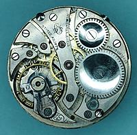 | |||
|
| IHC Member 1291 |
Picture 2; 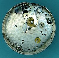 | |||
|
| IHC Member 1736 |
Great stuff, thanks guys. This makes perfect sense... although the watch is obviously swiss, the wind set mechanism looked distinctly american... turns out, that's because, it is. I had estimated the date for this Gruen to be 1900-1903 based on internet info stating this to be the period DG&S had a relationship with the Suisse watch makers. This patent date puts the watch no earlier than June of 1904 and likely later than October of 1906 https://ihc185.infopop.cc/eve/f...0082/m/605108602/p/3 | |||
|
| Powered by Social Strata |
| Your request is being processed... |
Welcome Aboard IHC185™ Internet Horology Club 185 IHC185™ Discussion Site Main Page Horological Discussions, Questions and Answers Pocket Watch Discussions Help finding US Patent 833489 (Edward Staehli - 1906 Stem-Wind and Set)
Horological Discussions, Questions and Answers Pocket Watch Discussions ©2002-2025 Internet Horology Club 185™ - Lindell V. Riddle President - All Rights Reserved Worldwide
| View $GS_USERNAME's User Profile | |
| View Recent Posts by $GS_USERNAME | |
| Notify me of New Posts by $GS_USERNAME |