
| WWT Shows | CLICK TO: Join and Support Internet Horology Club 185™ | IHC185™ Forums |

|
• Check Out Our... • • TWO Book Offer! • |
Welcome Aboard IHC185™  Internet Horology Club 185 IHC185™ Discussion Site Main Page Technical, Shop Talk and Internet Links Horological Tools, Books and Miscellaneous Looking for Opinions!! (Please see note in first post)
Technical, Shop Talk and Internet Links Horological Tools, Books and Miscellaneous Go | New Topic | Find-Or-Search | Notify | Tools | Reply to Post |
(Winder Note!! This winder, while it works great,is not one that would be easy to HOME construct. I have designed one, made from wood, that is well within the capabilities of many clock repairmen. Please look at this site. Current Winder Design Edited 2/18/07) Joe I have had this posted for a week and had few views and no comments. I changed the title to try again. Tell me what you think. (Previous title 'A Better?? Mouse Trap') Here is a picture of my latest project. This is one view of a mainspring winder I just completed. The brass disk is used after the spring is out of the barrel. More pictures follow. Joe 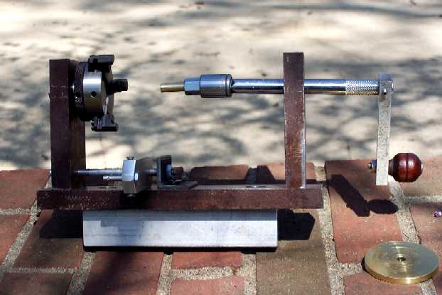 | |||
|
A different shot showing the lathe chuck that does the hard work. 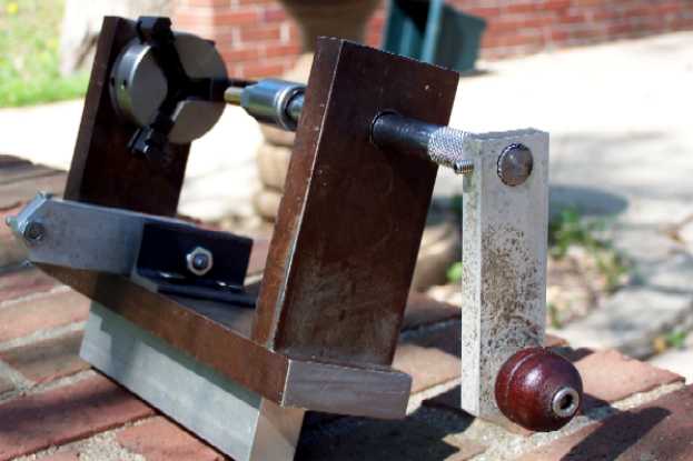 | ||||
|
Last picture showing the brass disk in place to help control the spring while removing and reinserting it in the capture sleeve. 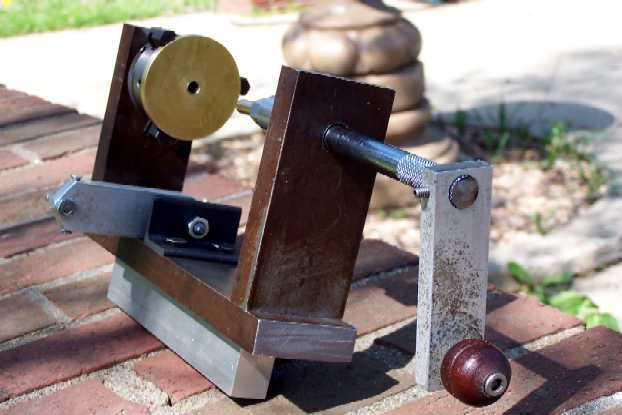 | ||||
|
And here is a long winded essay describing the making of the winder. I have been tinkering with clocks for about 40 years but never owned a mainspring winder. I always made do with a lathe or farmed out the ones I couldn't handle. While a lathe, with suitable tooling works fine, a 12 inch lathe is a little unhandy to use. This is especially true when working on smaller, barreled, springs. I deceided it was time to move up to a proper winder. Only problem was that after looking at what was available I could not find one. The Ollie Baker came closest but you still need three hands to operate it effectivly. I have been kicking a design around in my head for some time but just couldn't connect all the dots until I saw an add for a 2" three jaw self centering chuck for 20 bucks. (Same one that Clisby sells for $95) At this point it all came together. I checked my junk box and came up with a piece of cold rolled steel 5/8" by 2" and 36" long. More than enough material for the job at hand. While 5/8" material was considerably thicker than needed it was available. I cut 2 end plates and a base designing as I went along. I faced the ends of the plates in the lathe so they would be square and of the same length. I also drilled holes for the winding arbor and the mounting the chuck. I counterbored the end plate for the chuck so the chuck hub would be recessed into the plate. The chuck came on a tapered stud for use in a mini lathe. I turned this stud down and threaded it so that I could secure the chuck with a nut. The chuck was threaded onto the stud which made it somewhat directional. A spring being wound counter clockwise could start to remove the chuck from the stud. I drilled a small hole through the backplate and into the hub of the chuck and installed a pin so there would be no chance of this happening. I made the winding arbor by cutting the end off a 3/8" extension with a abrasive cutoff wheel and attached a handle. I added a bar to hold the end of the spring as it was being wound . It is designed to work on either side of the spring being serviced. I also included a post to handle loop end springs. This unit works them easily. At this time I have not added a rachet mechanism. While I have it worked out as to how I would do so I really can't see a need for it. The barrel or spring is held securely during winding so there is no need to release the crank handle. My left hand is free to work with capture sleeve or any other chore. I use a piece of PVC as a pad or innerface between the barrel teeth and the jaws of the chuck. This ensures that the teeth are not damaged. I have tested several barrel units, removing and replacing the springs many times and have had no slippage or damage to the teeth. I have made my own letdown keys and capture sleeves. While I can understand that some would not feel comfortable clamping on to the barrel's teeth I have no problem with doing so. My out of pocket expense for this winder is under $30. Thanks for looking and I hope I haven't bored everyone. Joe | ||||
|
Joe, This does indeed look interesting. I would like to see some pictures of it in action. As I understand it. The barrel is put in the three jaw chuck. The spring is then wound with the arbor substitute on the end of the crank. What holds the spring in place when you remove the barrel? Some pictures would help. Just me, sorry! Tom | ||||
|
Joe i am a clock newbie, but know a little about clock winders.It looks very thought out in design and the workmanship.The only thing i see is for one to acquire the chuck.Not often one sees one for 20 bucks. It is a great thing to have one that you feel confident and safe to use.It looks strong to handle the work easily. I like Tom would like to see the winder in different phases of winding a spring, removal and installing. | ||||
|
Winder in action. Ready to remove a spring from the barrel. 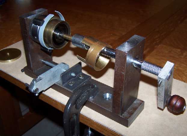 | ||||
|
Spring in capture sleeve. Home made sleeve by the way. 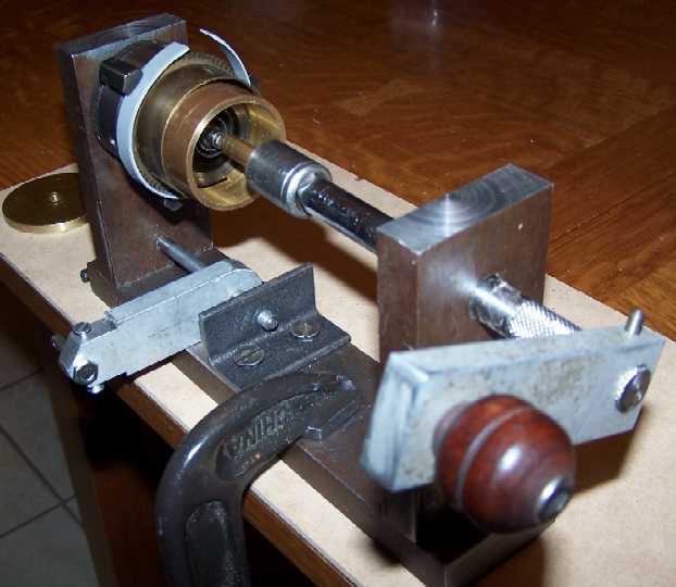 | ||||
|
Spring ready for cleaning or rewinding. 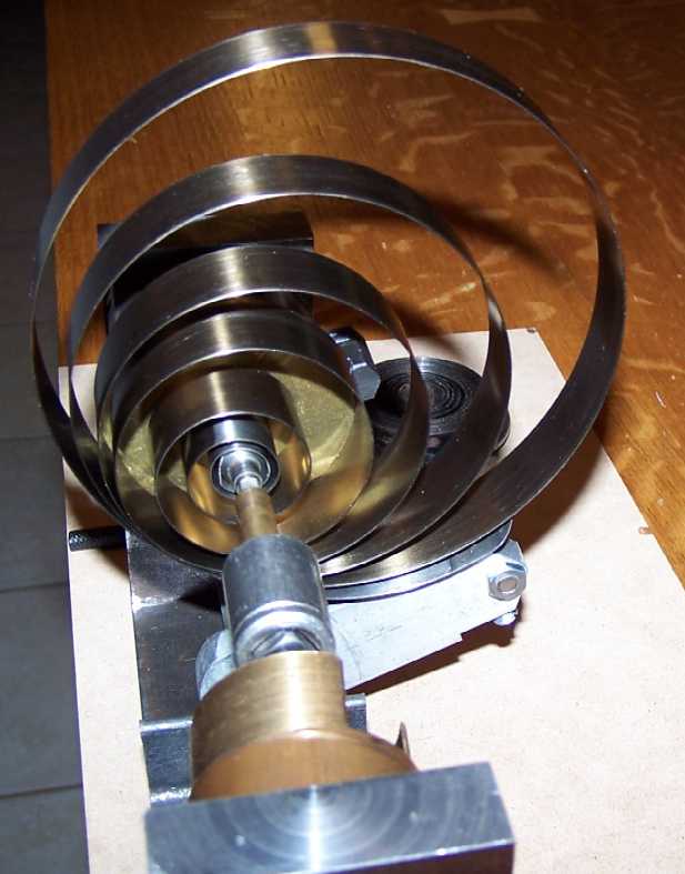 | ||||
|
Loop end spring ready to wind. 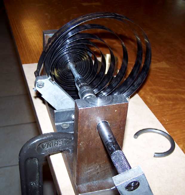 | ||||
|
Loop end spring in 'C' clamp. Note, I made up winding arbors for loop end springs as they are harder to handle with the great wheel attached. Hole end springs are handled with their own winding arbors. I made the letdown keys from a couple 5 way keys. Removed each key from the group and attached a suitable hex nut. 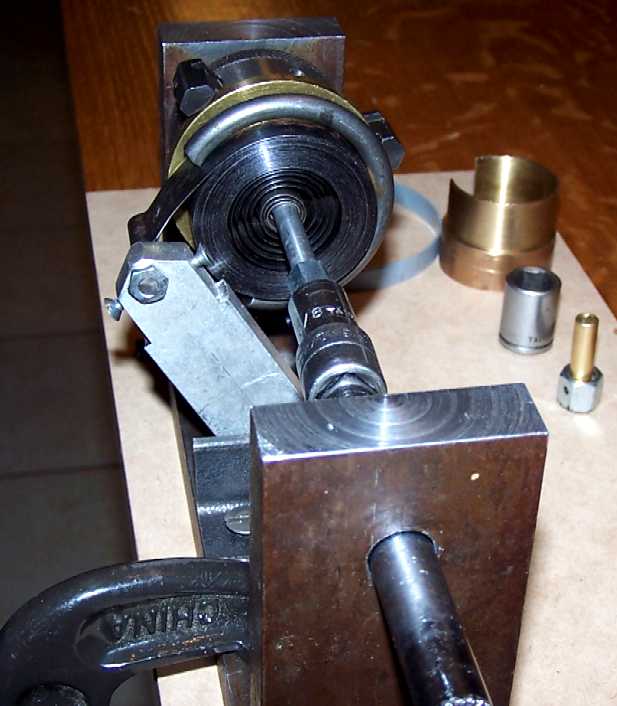 | ||||
|
Thanks Joe for the pictures , makes it much easier to understand.I think you have a great winder and maybe should patent your idea.This looks easier to use than the Ollie winder. | ||||
|
Joe, that looks very well done! Thanks for the extra pictures. It seems like it would be an easy system to use, and obviously, quite versatile. The use of the three jaw chuck to hold the barrel is a very good idea. You just have to get it in production now! Tom | ||||
|
Hi, I don't see a ratchet gear and click to hold the handle and spring when it is wound tight. Do you have to hold the handle and try to put the sleeve in while holding th pressure? Also you need various sizes of sleeves for various spring barrel sizes. Did you make several of these, if so, what did you make them from. | ||||
|
Hi Doug, Thanks for the reply. There is no rachet assembly as it is not needed. With most winders one hand holds the barrel while the other hand turns the crank. The rachet is needed to hold the spring so the cranking hand can install or remove the sleeve. With mine the three jaw chuck holds the barrel leaving one hand free to install or remove the sleeve depending on which direction you're going, removing or reinserting the spring. I can start with a capped barrel and have the bare spring in my hand, ready for cleaning, in under 3 minutes without resorting to rachets. I make my sleeves from whatever is available near the needed size. So far I have made them from brass pipe, (2 sizes) stainless steel pipe, (3 sizes) stainless tubing and aluminum tubing. It is very handy having a metal lathe and a well stocked scrap box. Hope this answers questions, Joe | ||||
|
| IHC President Life Member |
Get that rascal patented! Very interesting device Joseph. Lindell | |||
|
Hi Joe I'm not a clock guy, but from the pictures and description, it should work pretty good. Frank | ||||
|
Wow...I am very impressed by Joe's mainspring winder. Is there any way that I could contact him? Regards, | ||||
|
| IHC Member 659 |
Hi Naoki You can click on Joe's name then click on public profile and that has his e-mail address. Gary | |||
|
Gary, I tried but apparently I don't have the permissions? What do I need to do gain some permissions on this forum...? to overhaul a couple of clocks for members!? ( LOL ) Best Regards, | ||||
|
Hi to all those interested in Joe's mainspring winder, What is required for this winder to remove a mainspring from a barrel that has the arbour square drive on the same side of the barrel as the wheel (gear teeth). I'm assuming the arbour from the clock is used. If the arbour is reversed, it won't drive the spring. Peter Cork Newcastle Australia | ||||
|
Hi Peter, I believe you are refering to a spring that is on a cup not a true barrel. In case of these springs you must remove the great gear and arbor and either find or make a suitable arbor with which to work the spring. This problem is not just with my winder design but all the winders that normally use the existing arbor. I have made a few arbors just for this situation. I usually try to make one that has a movable hook so it can be turned and used in either rotation. Hope this helps, Joe PS, After rereading your post I realized you said the square on the same end as the gear as found in some Hermle movements. In those springs you will have to use a substitute arbor also. Joe | ||||
|
Joe, You have answered my question. I like the moveable hook idea Cheers Peter Cork Newcastle Australia | ||||
|
Hi Again Peter, I was trying to get this Current Design link posted before you replied. I didn't make it! Take a look at this one. I have had several requests for information on this one. I supplied all the metal parts for a chap in Tazmania who made all the wood parts himself. These winders are operating in England, Canada and Australia as well as the USA. Joe | ||||
|
| Powered by Social Strata |
| Your request is being processed... |
Welcome Aboard IHC185™ Internet Horology Club 185 IHC185™ Discussion Site Main Page Technical, Shop Talk and Internet Links Horological Tools, Books and Miscellaneous Looking for Opinions!! (Please see note in first post)
Technical, Shop Talk and Internet Links Horological Tools, Books and Miscellaneous ©2002-2025 Internet Horology Club 185™ - Lindell V. Riddle President - All Rights Reserved Worldwide
| View $GS_USERNAME's User Profile | |
| View Recent Posts by $GS_USERNAME | |
| Notify me of New Posts by $GS_USERNAME |