
| WWT Shows | CLICK TO: Join and Support Internet Horology Club 185™ | IHC185™ Forums |

|
• Check Out Our... • • TWO Book Offer! • |
Welcome Aboard IHC185™  Internet Horology Club 185 IHC185™ Discussion Site Main Page Technical, Shop Talk and Internet Links Clock Repair Questions and Answers Gilbert = A HUGE THORN
Technical, Shop Talk and Internet Links Clock Repair Questions and Answers Go | New Topic | Find-Or-Search | Notify | Tools | Reply to Post |
Sorry, I had originally posted this by mistake under the "Clocks Section". Early last summer a customer brought in several clocks to be repaired. Among them, a crystal regulator that was in pieces in a box. Customer stated that she had been having another person doing the repairs...but, she got tired of waiting for him to finish. I took the job. To start with...I thought "what was this guy thinking"?...with some of the "repairs" that had been made. I soon found myself in which I'm sure were some of the same predicaments(I can only guess of course). After having several gears and other parts made, that had been missing. And spending untold hours of work, searching, pondering and some thinking...I've finally got it working and keeping the correct time. The cost to the customer so far?...nearly $800.00(yes, I did explain to her that the clock was not worth it, well before). As hard as it is to fathom, I still lost much money in time spent with this thing. I began to put the movement in the case(which I also refinished)and found that there were even more screws missing((not from me). I attached the clock to the case...wiped everything off inside and out. Last thing was to attach the pendulum. WRONG!!! The pendulum is a little over an inch too long for the case!!!!!!!!!! Even with the suspension spring removed the pendulum touches the bottom of the regulator! Now I have to call the lady. What do I say to her? I'm so bummed! 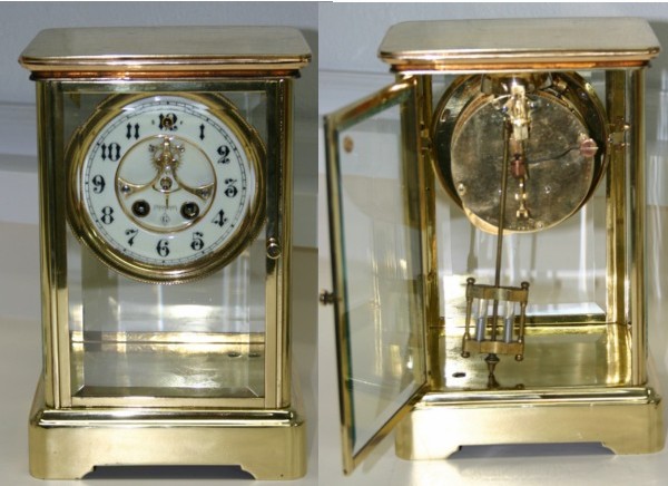 | |||
|
Greg,just a thought.Do you think repair guy #1 inadvertantly put the wrong pendulum back in that box of parts when he gave that anniversary clock back to your customer?I certaily wouldn't be above contacting him or her and explaining your dilemma.These things do happen.It sounds to me based on the missing screws that this clock was scattered on a workbench until he got tired of fooling with it and just picked up anything that resembled Crystal Regulator parts and threw them in a container.Just my own thoughts. I will say your work looks damned nice,but ain't that the way it always is with the best laid plans.It's always something. Good luck with your pendulum dilemma.I hope all turns out well for you. Respectfully,Bob Fullerton | ||||
|
Thanks Robert, I try. You should have seen it before! Of course, I forgot to take before photos. It would be nice if it were only the pendulum...it certainly would be easier to "fix". The problem is: the pendulum is correct for this movement...at least as far as time keeping is concerned. Gilbert made two of these clocks that were "identicle"(from what I can see anyway). The "Valerie"(9 3/4"h) and the "Vista"(10 3/4"h). I am referencing to "Tran"s Gilbert book, page 112 and 113. This could explain the 1" difference in the pendulum. Must be they switched a gear or two to compensate for the pendulum length. Either this is the wrong case for the movement or the movement is wrong for the case. Considering the problems that I've had in getting the movement to run...my bets are that the movement was switched. Also missing from the box of parts were two of the bars(top and bottom)that hold the beveled glass, the bottom pendulum nut, one of the knobs that secure the pendulum pieces together, screws too numerous to mention. Oh, and the decorative piece that screws onto the bottom of the gong...which I will have to make yet. Does anyone have a photo of this peice? I've contacted the customer She's(as well as I)also very concerned about all of the money that its costing(she hasn't paid any yet). I don't belive that I will ever work on another one of these movements again! If I do I'm going to charge an "aggrivation fee" : | ||||
|
Greg, Here's the gong base. This is actually from a "Falmouth", but the Falmouth is the same as the Vista, except for the top and base. (I had a Vista for awhile, but sold it about a year ago.) Let me know if you want the exact measurements. 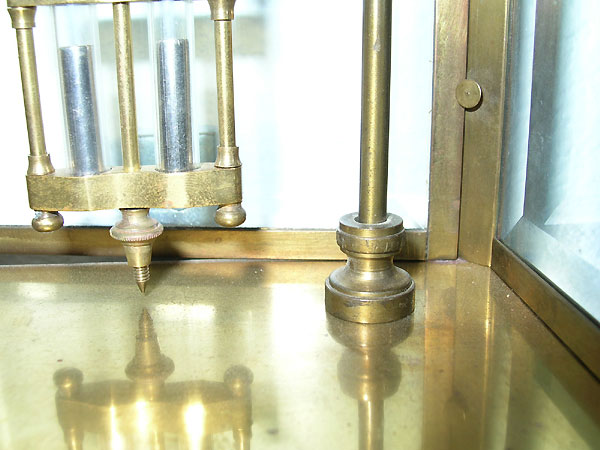 | ||||
|
Just to complete the picture... Here's the entire clock... I spent A LOT of time on this one, too. This was actually the first clock I bought when I started collecting. The problem with these movements is that, when the time side mainspring breaks, it usually causes a lot of damage. The last person that worked on this one apparently thought that everything could be fixed with solder. (And, if that didn't work, try more solder!) It still needs some more work. Cosmetically it is now very clean, but still doesn't run consistently. One of these days I'll tear it apart again... 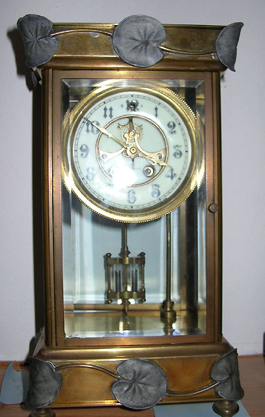 | ||||
|
Dave, That's a very pretty clock! I'm not sure what originally had happened to the clock that I have, but, I suspect that your correct. During the time that I had it the mainspring hook broke, and yes the 1st,2nd and 3rd wheels took the hit. There had been lots of solder used on these same wheels prior to my getting the clock. I had a new mainspring gear made, new arbors for the 2nd and 3rd wheel as well as new lantern pinions, bushing on the 3rd wheel pivot. Trouble was that there was no protection from the mainspring, cannot use any kind of device to "keep" the mainspring for removal or replacement...must be done by hand. The end of the mainspring is held in place by very thin brass. I hope never to have to take it apart again. It looks like I did a pretty good job on the bottom pendulum nut. I don't remember what or if I had a "model" to work from but it looks pretty close. Yes, I would like the dimensions of the gong base, just the diameter and height should be sufficient. Thank You | ||||
|
Greg, The diameter of the lowest part of the gong base is 15.8mm, the diameter of the highest part is 10.8mm. The height is 16mm. | ||||
|
Thanks Dave, Could you do me one more thing? Could you measure the length of your pendulum rod? Thanks | ||||
|
Looks like about 6 1/8 inches, Greg. | ||||
|
Hello All, I saw a French one of this type clock a couple of years ago and obviously something similar to this situation had occured because there was a slot cut in the base to allow the pendulum to swing clear, I know it's not the ideal way out but it made the clock run again and dust doesn't fall uphill. Regards, Ged. | ||||
|
I've been able to aquire a junk movement of this type. After measuring dias. and teeth...this is what I've come up with: on the working movement Escape wheel = 25 teeth and 6 pinions 5th = 35 teeth and 8 pinions 4th = 35 t and 7 p 3rd = 35 t and 8 p 2nd = 48 t and 8 p 1st = 64 t Pendulum length = 6 1/8" new movement: escape = 26 t and 7 p 5th = 35 t and 7 p 4th = 35 t and 7 3rd = missing 2nd = 48 t and 8 p 1st = 64 t Pendulum = missing my question to the mathamatically inclined...if I used the 3rd wheel from the working movement(assuming it would mesh correctly)would the "new" movement require a shorter pendulum? many thanks in advance! ps. I'm also going to post this to the clocksmiths web site. | ||||
|
Hi Greg, If you visit the BHI site, there's a clock train calculator you can use, may be worth a shot Best regards John Woolsey http://www.bhi.co.uk/hints/bph2.htm | ||||
|
Sorry, forgot to add this one, bucket loads of horological and other 'on-line' calculators here! http://www.martindalecenter.co...s1_1_CatoClocks.html Also: http://onlineclockbuilding.com/ Scroll down the index on the left to 'Software' for downloadable calculator. Enjoy! Best regards John Woolsey | ||||
|
Good Morning. An Update on this movement: I did attempt to change gears, but the "new" gears needed as much work as the original ones...so decided not to do it. Thanks for all of the information. However, while gazing at it the other day...I had a brain storm(or stormy brain). Anyway...take a look at the photo below. I turned the regulator upside down, placed a stronger spring in it, so as to keep the reg. wheel and gear tight, added some spacer to fit and attach the regulating unit to the movement, and am using a much weaker suspension spring. This combines go give me almost 5/8" more room for the pendulum to fit in the case. I'm hoping that the thinner sus. spring will allow me to gain just a bit more. I know this is not the correct way to "repair" a movement...but! There is no damage being done to either the movement or case. What do you think? Any more ways to gain space between the end of the pendulum and floor of the case? As Always Thank You Greg 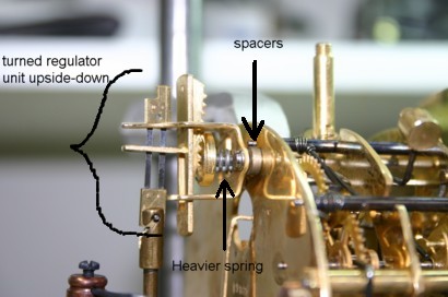 | ||||
|
| Powered by Social Strata |
| Your request is being processed... |
©2002-2025 Internet Horology Club 185™ - Lindell V. Riddle President - All Rights Reserved Worldwide
| View $GS_USERNAME's User Profile | |
| View Recent Posts by $GS_USERNAME | |
| Notify me of New Posts by $GS_USERNAME |