
| WWT Shows | CLICK TO: Join and Support Internet Horology Club 185™ | IHC185™ Forums |

|
• Check Out Our... • • TWO Book Offer! • |
Welcome Aboard IHC185™  Internet Horology Club 185 IHC185™ Discussion Site Main Page Horological Discussions, Questions and Answers European Pocket Watch Forum DIY watch repair
Horological Discussions, Questions and Answers European Pocket Watch Forum Go | New Topic | Find-Or-Search | Notify | Tools | Reply to Post |
Another type of dial foot retainer used on these and many other Swiss watches, is a knife edge type screw. This screw has either a flat or a notch milled on one side to clear the foot. The dial feet protrude through the dial plate, and the screws, which are set close to the edge of the feet are turned, causing the knife edge of the disc to cut into the copper foot. As the screws are turned further, they pull on the feet so pulling the dial tighter to the dial plate. The danger is that if a dial foot is pulled too far, it will draw the copper back of the dial (to which the dial foot is welded) away from the enamel, breaking it up in the process - a Very common sight being holes in the dial enamel over an overtightened foot. The dial screws are actually turned 'Anti-clockwise' to tighten dial feet, and 'Clockwise' to loosen them. So to loosen the dial foot to remove the dial, the screw needs to be 'tightened' into the dial plate - but only sufficiently that the 'flat' or notch releases the foot.! Sometimes the flat won't clear the foot even when tightened fully against the dial plate, so you have no option but to go the other way, and hope the flat will clear the pin and release it before the dial breaks! The photo below shows a typical knife edged screw with a circular notch. John 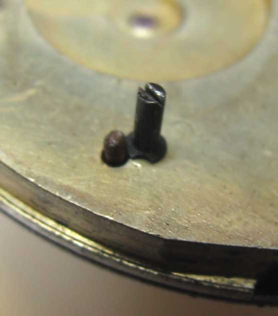 | ||||
|
The 'giveaway' (and often 'boobytraps' for the unwary) on 3/4 plate movements like yours that there Are screws securing the dial feet, is an 'extra' srew head visible on the backplate, as in the photo below. (Arrow A) John 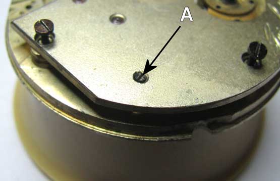 | ||||
|
Having got the dial unfastened, place the movement dial up on the movement holder, and gently work the dial off the movement, often they will take a bit of shifting if a gorilla has overtightened a dial foot and bent it! With the dial off, you will then see the motionwork which drives the hands. This is basically a 12:1 reduction gear on a watch with a 12 hour dial. It would be 24:1 reduction for a watch with a 24 hour dial! So for a 12 hour dial, and for every full turn of the cannon pinion (Minute hand), the hour wheel (Hour Hand) moves 1/12th of a revolution of the dial and is represented by hour markers, which also correspond to each 5 minutes marked. The gears are calculated and cut to accurately represent this, so the gears from one watch will not necessarily work in another, and in the case of Swiss watches, it will be almost akin to winning the lottery if you Do find a match! Try not to damage or lose them! John 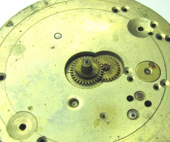 | ||||
|
The next shot shows the component parts of the motionwork lifted off. At the centre of the movement is the cannon pinion, which is driven by the train of the watch. The large wheel with the smaller gear at the centre is the 'minute wheel' and driven by the cannon pinion, which in turn drives the larger gear which has the 'pipe' at the centre. This last gear is the 'hour wheel' onto which the hour hand is pressed. The smaller gear in the centre of the minute wheel, is the 'Minute Wheel Pinion' The minute hand is pressed onto the small diameter pin, seen protruding through the centre of the cannon pinion. The small belled washer, is a 'dial washer' which is situated between the dial and the hour wheel, acting as a small spring to keep the hour wheel in in contact with the cannon pinion and Minute Wheel. Without this washer, and because of the clearance between the dial and hour wheel, there is a tendency for the hour wheel to lift clear of the minute wheel pinion which drives it, stopping the hour hand moving! Let me know if you're with me so far! John 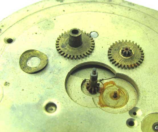 | ||||
|
John you’re amazing, I reckon there’s more than me watching this, if so would be delighted to hear from you, I shall try to digest this lot John, it will certainly keep the brain box going, thanks again for your encouragement and patience, All best Wishes Les | ||||
|
Many thanks Les, it always makes the effort worthwhile when folks express their appreciation! I'm little more than an interested amateur really, but I've been around these types for a while now - and seen most of the botches and damage that can occur on them. If my musings help someone save a few quid by avoiding buying a dog - or turning a good watch into one, it'll have been worth it! John. | ||||
|
At this point we can't split the plates yet, because the cannon pinion and hands setting pin will hold it all together, even if the plate screws are removed. The next step is to knock the pin through the cannon pinion and remove them. A digression here first! There are basically 3x types of centre wheel and pinion assemblies used on Swiss watches, depending on their age. Knowing what yours has will help avoid damaging a watch! Early Key set watches like yours, have a key square to set the watch from the back. This square is on the end of a taper pin which is a light friction fit in the hollow centre wheel post, and which extends beyond the dial plate sufficiently for the cannon pinion to be pressed onto it, and leave a small stump for seating the minute hand. A second variation on this, is on a Stem wind Pin set movement, which has the same pin, but No square, it will be a small dome instead. Not seen many around, and I suspect it was a transition between key and pin set movements, which would have allowed watchmakers use up the earlier type 'hollow' centre wheel pinions. It is virtually impossible to remove a cannon pinion on these with a pin chuck, the pins have to be knocked out same as a key set type. If you try twisting the cannon off one of these pins, you'll twist the taper pin and break it! The giveaway will be the visible stump in the centre of the cannon pinion for the minute hand. This goes for Swiss 3/4 plate or bar movements anyway! The third type, has a one piece solid centre wheel post and pinion, in which the cannon pinion is a snap fit on the post extension, there is no pin to knock through. Leaving the cannon pinion in place when splitting the plates, will in most cases simply hold the centre wheel in place on a plate or bridge. The first photo, is of the hands setting pin and cannon pinion, to illustrate what you will be removing! John 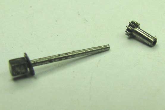 | ||||
|
This shot shows the pin through the hollow centre post, with the cannon pinion placed on the end. The eagle eyed amongst you will no doubt spot the outrageous amount of wear on the centre wheel pivot! This is a common sight on non jewelled centre wheels - and if you find rust in your watch like there is in my example, you can expect to find similar wear! John 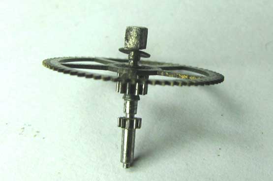 | ||||
|
Ok, so having set your movement 'Key square down' on a movement holder, lightly tap the end of the pin (arrowed) with either a small watchmaker's hammer, or using a small punch too if you have one, and it should drop through. These are generally not too tight! Lift off the now loose cannon pinion and place in your parts tray with all the other bits you've removed so far! Then turn over the movement, and draw the pin out - with its dust cap (washer) if it has one! 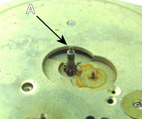 | ||||
|
A point worth mentioning here about key set watches that appear to have no key square - ie: broken off! First of all, key squares Will snap off like carrots if you push the key over on them too hard when setting a watch! It is not the end of the world for a watch if this is broken! Watches often turn up on eBay in this condition, and folks avoid them because they might be terminally un-repairable! These pins can quite easily be filed up by hand from blued steel pinion wire available from watchmaker's supply shops - or any suitable steel rod you may have kicking around. All it needs is for you to be able to file a passably square head on one end (to suit your key), and reduce the rest to a shallow taper to suit the hole in the centre post and the cannon pinion. Once you've got your 'eye in' these can be made in less than half an hour using little more than a pin chuck and a decent small flat file! John | ||||
|
Next step is to take out the plate screws, and lift off the backplate. In the example I've shown below, the centre wheel has come off with the plate - this is because the wear and dirt on the pivot is binding it in the pivot hole. Hopefully, the plate on yours will lift off leaving the wheel behind. If it does start to come away with the plate, you can gently push the wheel down with a bit of pegwood or a toothpick at the centre to keep it in place. Using a screwdriver to do this could gall or distort the wall of the pivot tube as it's quite thin at this point, so preferably use something softer than steel. John 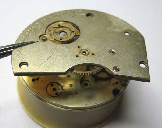 | ||||
|
And this is what you should see when the plate is removed! The gear train in all its glory! In this example, the escape wheel is already out, so don't panic if my photo doesn't quite match what you expected to see! John 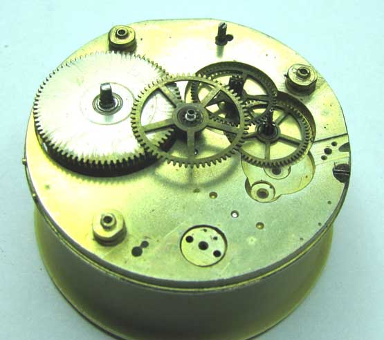 | ||||
|
This is a cylinder escape wheel! This shot illustrates why the cylinder itself has an 'L' shaped slot in its wall! The head as well as the post it sits on has to enter the cylinder! John 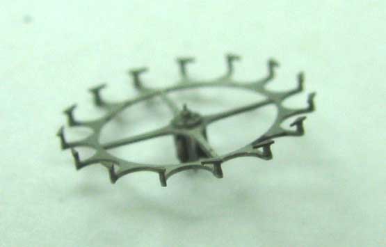 | ||||
|
Hello John, This is to thank you for all your hard work over the last few weeks Will be signing off now for the holidays, God willing I shall be back in the New Year, May I take this opportunity to wish you and your Family, and all members of the I H C a Very Happy Christmas, & a Peaceful New Year Best Wishes to All. | ||||
|
Many many thanks for your kind wishes Les, they're Really appreciated. Wishing you and your family, and all IHC members and interested 'readers' a Very Happy Christmas and a Wonderful New Year also. John | ||||
|
John, What a wonderful, interesting read. Thank you for your time, dedication and patience to document the progress for us. Ray | ||||
|
Ray, Many thanks for the great complement, Really appreciated. Plenty more to come yet too, just need to get a few more pic's done ........ John. | ||||
|
Hello all you folks that have been following this thread, After a word with John Woolsey the project has been scrapped, Mangled hair spring could have got away with, broken pivot doubtful, the bottom plate so badly scored impossible, Time not wasted though learnt a great deal, and still learning, Thanks one and All Best regards Les 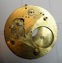 | ||||
|
Hi all, and a belated Happy New Year to everyone. After a dreadful amount of illness over the last month or so, I'm finally getting up and around again, hope soon to have a bit more spare grunt left over to do a bit of posting again. Although Les has binned his 'example' movement, I'm going to carry on with the topic and see it through for those of you that have been following it so far. May be a few days before I post the next part, but post it I will. Thanks all for your patience. Best regards John | ||||
|
| IHC Life Member Site Moderator |
Hello John Good to hear from you, take your time & gather your strength. Glad you are up & about, I always miss seeing your posts. Be well my friend! Tom | |||
|
Thank you Tom, your comments and wishes are always appreciated. There'll be a bit of 'bedtime reading' on its way to you shortly, plus more to follow! Taking a slight step backwards on the topic, I'll cover taking off the escape wheel cock, as it is deserved of a special mention = if only to prevent the unwary wrecking a movement! Depending upon your movement, and whether or not it has a sub seconds dial, removal of the fourth wheel ('C' shown under the escape wheel) may depend upon the escape wheel being removed first. This is because the close proximity of the 4th wheel to the underside of the escape wheel, plus the seconds hand pinion extending a long way through the jewel (or pivot hole) doesn't allow sufficient clearance for the gear to be lifted out. If no seconds hand pinion is there, then usually there's room for the 4th wheel to lift out as the pivot is short. The escape cocks on cylinder types, are usually only held by one screw (A), but on the underside there are two quite deep locating pins, which can occasionally be quite tight. Please don't wedge a screwdriver under the jewelled end to prise the thing off! Chances are if you've got tight pins there, you'll snap the escape cock in two - or at least bend it! It may look a beefy chunk from the top, but the next images will show just how fragile this piece is! More to follow after the image John. 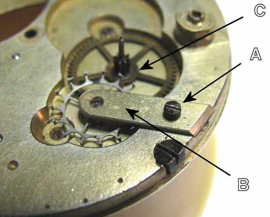 | ||||
|
As you can see on the image below, the underside of the escape cock is relieved, this is to clear the tops of the escape wheel teeth - which substantially reduces the thickness of an already fragile brass casting! As the locating pins are much deeper than the thickness of the relieved area of the escape cock, there is a danger that prising it up from the jewel/pivot end, will break it before the pins are clear! This one has had the relief area machined quite nicely, many however, you will find have been hacked out with a file or graver - possibly to accommodate wear on pivots and jewel holes (and escape wheel tilting over), which means the wall thickness at the thinnest point can leave you wondering if it's only the gilding holding the piece together! So why so thin! Because the escape teeth act virtually on the centreline of the balance, it doesn't take a genius to work out that the balance rim by default, has to swing over the top of the escape cock. Because ebauche makers try to keep the height of movements low to keep watches thinner, by necessity, the escape cock has to be as close as possible to the dial / pillar plate, to keep the height of the balance rim and cylinder to a minimum! John 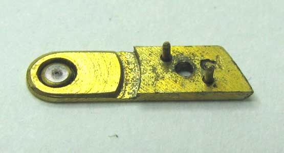 | ||||
|
| Powered by Social Strata | Page 1 2 3 4 |
| Your request is being processed... |
©2002-2025 Internet Horology Club 185™ - Lindell V. Riddle President - All Rights Reserved Worldwide
| View $GS_USERNAME's User Profile | |
| View Recent Posts by $GS_USERNAME | |
| Notify me of New Posts by $GS_USERNAME |