
| WWT Shows | CLICK TO: Join and Support Internet Horology Club 185™ | IHC185™ Forums |

|
• Check Out Our... • • TWO Book Offer! • |
Welcome Aboard IHC185™  Internet Horology Club 185
  IHC185™ Discussion Site Main Page
  Horological Discussions, Questions and Answers
  Clocks, Including 400-Day Discussions
  S.Hart Devizes, Longcase Movement Restored.
 Internet Horology Club 185
  IHC185™ Discussion Site Main Page
  Horological Discussions, Questions and Answers
  Clocks, Including 400-Day Discussions
  S.Hart Devizes, Longcase Movement Restored.
Related Content: "Time on My Hands" Restoration Projects
Go  | New Topic  | Find-Or-Search  | Notify  | Tools  | Reply to Post  |  |
I suppose some folks might find it odd that I should appear here showing a clock resto' project when I'm more usualy haunting the European watch forum, but few know that it was clocks that got me into watches! Funny old world really I won't bore everyone with the quirky story behind how I came to restore this clock, suffice to say I was looking around a barn at a friends house where I spotted it - and brought about a very enjoyable challenge for me bringing this piece of history back to life. I'll be posting pic's and a description of the work in the restoration forum, but here's a few taster pic's for you to pore over. I've also got the owners blessing to post the pic's too, Many thanks to them for their approval. Best regards John 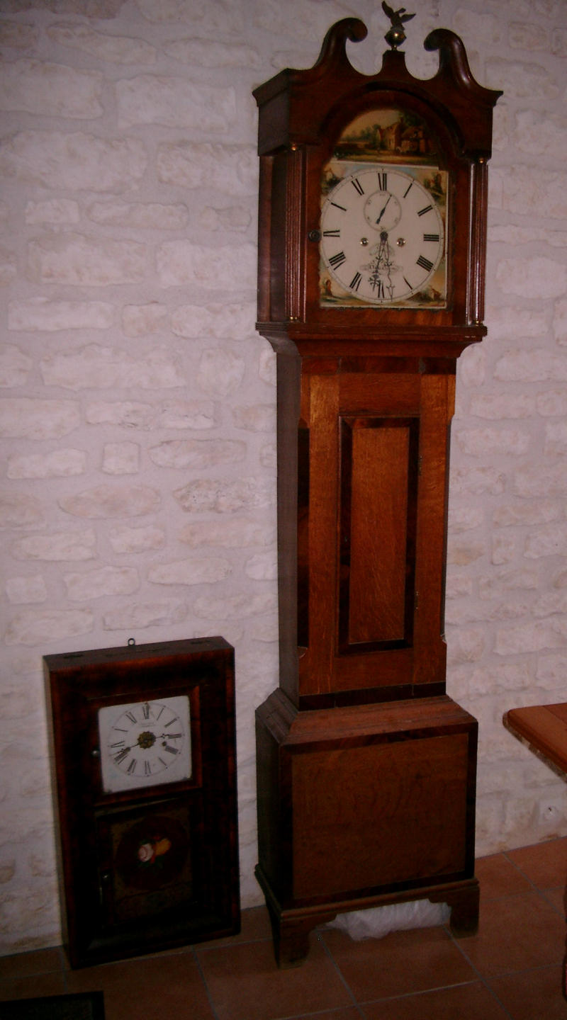 | |||
|
A rather grubby well worn movement! 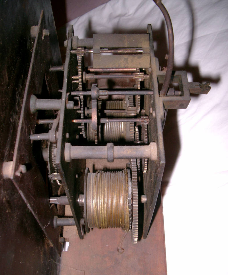 | ||||
|
Front plate exposing butchered winding drum pivot holes and other dragons lurking within! At least it wasn't a marriage! John 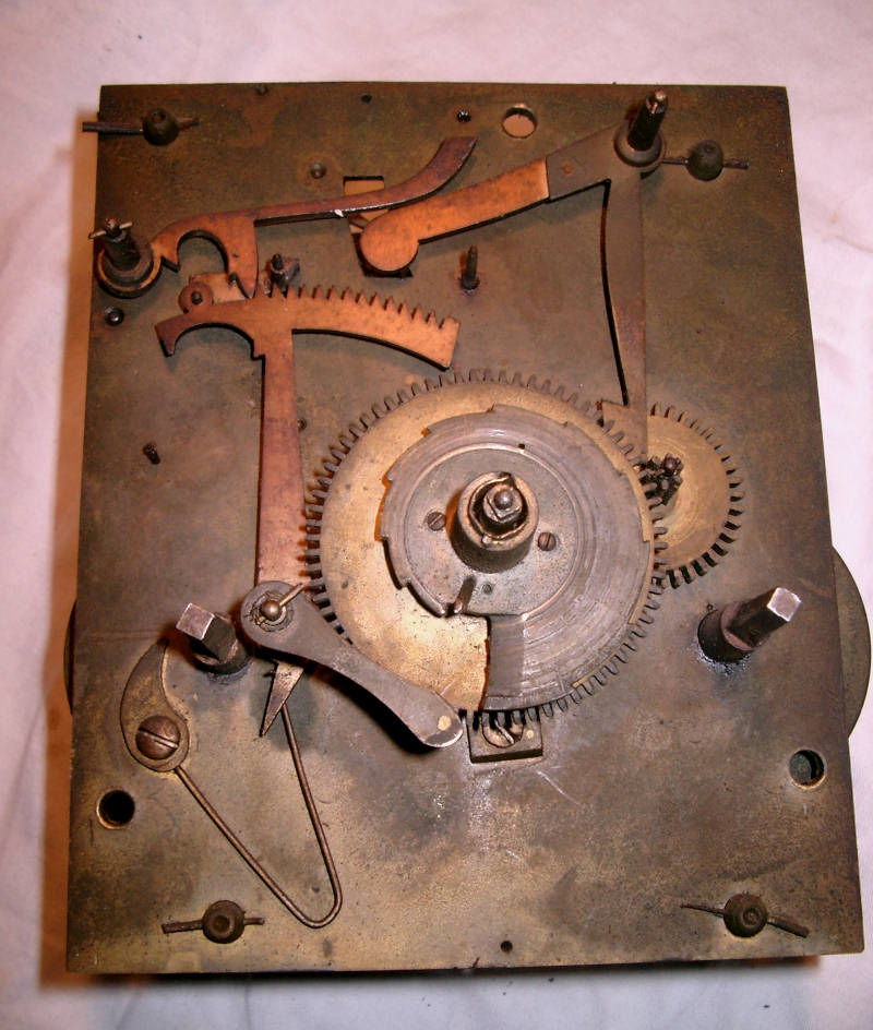 | ||||
|
Cleaned up a bit ......... and it works too! John 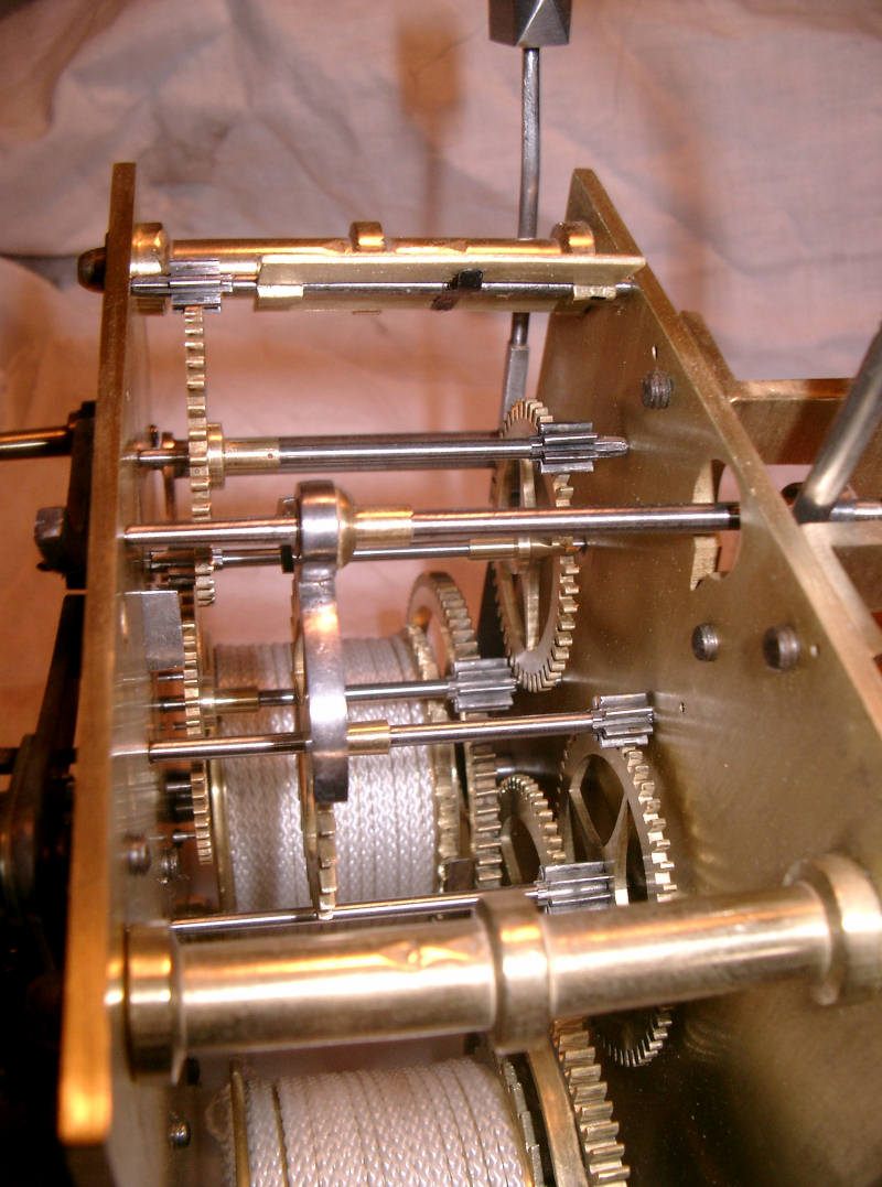 | ||||
|
Shame to hide it all under a hood, but there you go! A lack of certain tools and only a watchmakers staking kit for bushing made it a challenge, but those old boys in 1850 had less gear than I had, so I'm not complaining. I did have my Boley with me, but all of the pivots had to be hand filed and burnished the 'old fashioned way' rather than turned between centres. All in all a lengthy repair covering practically everything that could wear out / go wrong with a 19th century longcase - and I loved every minute of the job! John 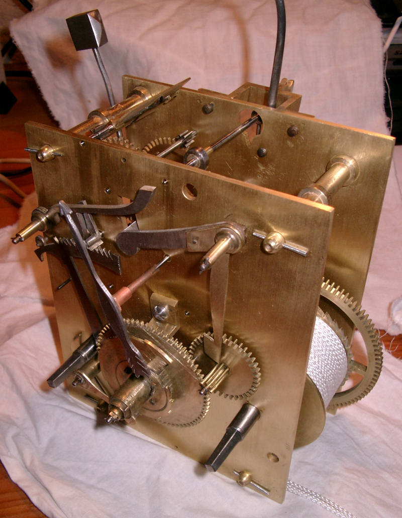 | ||||
|
| IHC Life Member Moderator |
Truly beautiful workmanship, must give you quite a feeling of accomplishment. I find the string rather than cable an interesting touch and I'd like to learn more about that decision. Don | |||
|
Don, Thank you for your very kind comments, they are really appreciated. Probably the biggest buzz of accomplishment I got out of the restoration, was fitting the movement into the clock, winding it up, setting it in beat and having it run and chiming for the first time, all in the presence of the owners and their parents. The clock had been gifted to their parents by an old gentleman they'd cared for, and whom had never seen it run or chime - no one had. The parents had in turn gifted it to the current owners and were due to return home the following day, so I was a tad up against the clock getting it done in time if they were to see it come alive. I estimated I'd take around a month to do the job, it took 6 weeks in the end! The string came about via a combination of a blunder by me, and a pragmatic decision between myself and the clock's owners. When I collected the movement, I was given two packets containing lines which were intended for the Welch wall clock standing at the side of the Hart, and which I thought would be long enough. They were woven synthetic lines intended to replicate gut lines. What I hadn't twigged until I'd got the movement done and ready for stringing, was that whilst the lines would reach the weights near the floor, they also actually had to go around pulleys the weights would be suspended from, and back up through holes in the seat board where they're knotted! Now faced with the prospect of an 8 day clock running for maybe 3 and a half, decided to hunt around for suitable cable. A local DIY retailer had rolls of woven nylon cord intended for drapes which could be cut to any length, so 5 metres later and it was suspending a couple of 5 kilo cast iron weights! I think the cord is likely to stay in the clock for a while though, because the clock case has been damaged by the weight smashing the base out of the foot, so there've been some bad gut line breaks - this is also backed up by a considerable number of bent teeth on both the time and strike trains - and the remnants of frayed gut line tied up inside the clock. The purists may not like it, but they don't have to cope with being scared whitless in the middle of the night by a 5 kilo weight slamming into nice new ceramic tiles when a cable breaks. At the end of the day, cable is a cheap easily obtainable consumable (when planned for) and easily reversible, so for now at least, they'll be staying put. John. | ||||
|
A beautiful job. I like the cord. Bob | ||||
|
Nice work John. It looks like a beautiful movement. Be proud of yourself.. Bill Carlson | ||||
|
| Administrative Assistant |
Thanks John for sharing your restoration with us. Nice job! Debbie | |||
|
Thanks for the comments all, and apologies for the delay updating the topic. Having posted the 'taster' of what is to come, it's been a bit of a poser deciding where best to begin the description of the repairs to the movement, so I'll generally cover what I was confronted with when I first 'met' the clock. First up was the appearance of the hammer hanging over - outside the plates. It had been deliberately disengaged so the tail of it's lever was clear of the train, and the winding drum also wired up, so something was certainly amiss there - especially as there was a trail of frayed gut line hanging off the drum!. Having got the movement out of the case and into daylight, a quick glance at the 'Fly' - which controls the speed of the 'strike' by acting as an air brake, clearly wasn't doing its job and had been more intent on boring an exit through the back plate! JW. 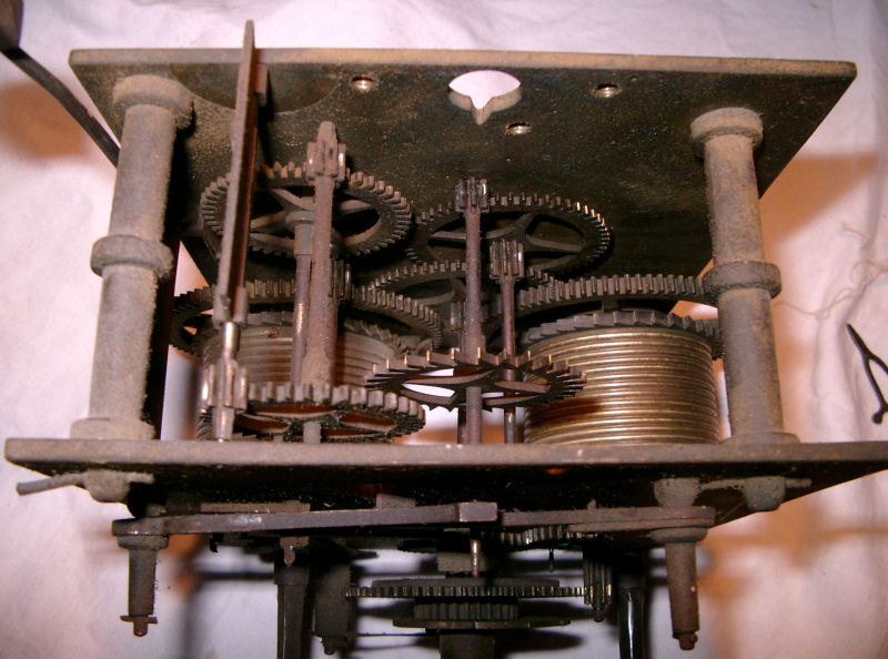 | ||||
|
A quick 'flick' of the 'Fly' and it rotated freely also exposing the reason why it was freewheeling! The brass retaining spring had broken - and had been that way for qite some time. This was originally a thin strip of brass rivetted to the fly plate, which had the dual purpose of both locating the fly in position to prevent it shifting along the arbour, and as a friction device which could be adjusted to increase or decrease the pressure it bore on the arbour - and hence the speed of the strike. In the absence of this spring, and consequent 'freewheeling' action of the fly, plus the action of a 5 kilo weight, what would usually have been a pleasing bell chime, must have sounded more like a Fire Bell .......... that is, until the strike work on the front plate would have stopped it dead ........ JW. 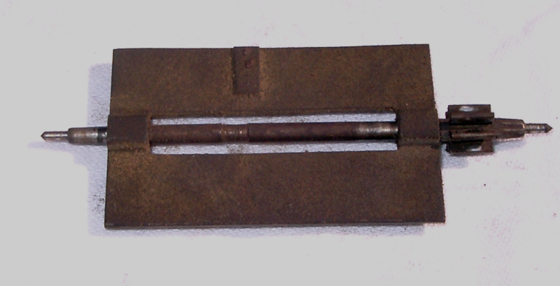 | ||||
|
As can be seen in the photo's, the condition of all the parts was fairly sooty and rusted at best, plus some well worn pivots, all of which had to be resurfaced and burnished, plus the corresponding holes in the plates re-bushed. Numerous attempts were made to replicate the missing brass spring, and all examples I made broke when attempting to increase spring pressure by bending. As these strips all had to be hand filed from larger pieces, a lot of time ended up in the waste bin unfortunately. Having wasted nearly a day over this part, I decided that continuing with a brass spring was simply storing up a problem for the future, and decided to make a spring from a piece of pocket watch mainspring. This was anealed, punched for rivets, shaped around the arbour, then re-blued along its length. It took a couple of attemts to get it right, but in the end worked very well. Crucialy, this is also a totally reversible repair should a future repairer decide to take it back to it's original design! As well as cleaning up the brass plate, the holes for the arbour were also repaired, which wasn't too easy as they had to be sized to the arbour which had a different sized diameter shaft at each end! - fortunately my reamers went through from both ends for both bushings sufficiently to get them to size! The pivots were also refinished and burnished and the corresponding pvot holes re-bushed. Unfortunately, although the pinion teeth cleaned up ok, I was unable to shift any of the train wheels so as to work on an unworn section of leaf! JW. 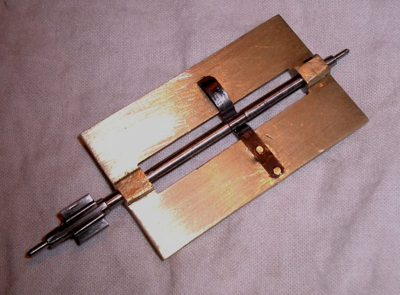 | ||||
|
The next shot shows fairly typical damage to the winding squares, both winders were pretty much as bad as each other. Because the winding shafts are generally slightly tapered, and if the winding key isn't pushed fully home before winding, it will slip over the corners. Eventually this damage results and the key hole gets stripped out too. If the key does slip, this can cause further damage when the ratchet teeth smacks back into the click, and if the click breaks, the weight is then free to rocket to the bottom of the case - and if it catches you out, can give knuckles a nasty rap as the key tries to emulate a propellor! A 'winged' type key similar to those used on mantle clocks was used to wind this one rather than a crank, so if that slipped, could cause a very nasty injury indeed. It now uses a proper crank handle. | ||||
|
The repaired square! I use small diamond files these days for the grunt of the metal removal, as some of these squares are almost diamond hard and crucify standard files. I then finish off with 'buff sticks' made using flat strips of wood (worrn out commercial sticks) and self adhesive alluminium oxide papers of 180 grit, finishing off with 600 'wet and dry' to give a satin gloss. The 180 grit papers I use have a very uniform bonded grit which doesn't break down and scour the surface, and the 600 easily removes the fine scratches left. I usually also break the corners slightly as it looks cleaner and prevents the key jamming on a sharp edge. A trick I found for getting the squares dead flat, was to use an anglepoise lamp at low level so the light just bounced across the surface of the 'flat', you can see quickly where the file is cutting and adjust the cut accordingly. These were all hand filed without a filing rest - just secured in the lathe headstock with the square resting on a Jacot adaptor. (Motor turned off to avoid mishaps)! This job was also done before filing and burnishing the pivot surfaces, which in this case, needed very little work at all. All the wear was in the holes in the plates. John 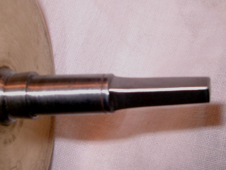 | ||||
|
And this is the pivot hole the winding drum was working in! This shot also shows a typical botch repair that makes any enthusiastic clock repairer cringe - and conservatores feint if it's a rare item! The well meaning soul that did this little 'mod' never really thought through the purpose of his intention, other than to close up the hole sufficient to stop the shaft rattling around. He actually punched the TOP of the hole and not where the wear Actually was - at the Bottom! I always work on the premise that whatever you do to a clock or watch mechanism, never do anything that can't be reversed or improved upon by someone better at the job at some point in the future. This sort of damage can't be removed or reversed without taking a huge chunk out of the plate by a massively oversized bush, so it stays for posterity as an example of how Not to repair a pivot hole! The wear here was such that the hole was fully 1.00 mm larger than the shaft. John 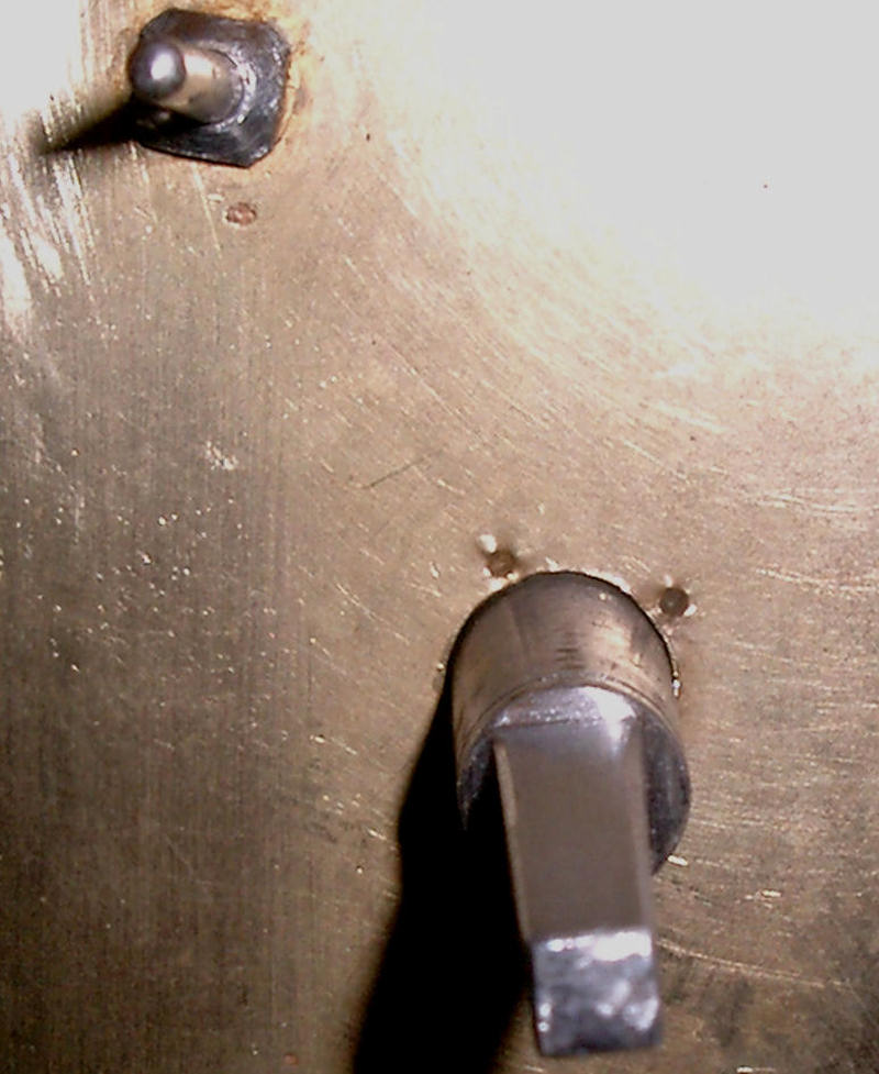 | ||||
|
The resulting repair. Didn't quite get away with an invisible repair, as the edge of the new bush is Just visible. Before the bush was fitted, the 'spikes' from the punch marks had to be filed off, as they protruded into the hole quite a way and would have thrown the broach out of kilter to the hole. Also had to turn up a new brass bush as I'd nothing available that was big enough. John 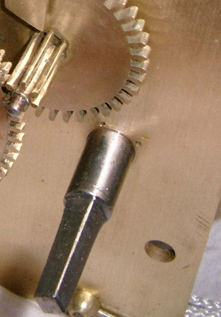 | ||||
|
Classic 'Hourglassed' pivot! Quite a few were in this state, and had to be hand filed in a Jacot tool in the tailstock. These pivots when they've been in service for a century or so become glass hard, and will ruin an expensive pivot file very quickly. I always use a diamond file now to get through the hard shell, then finish off with a pivot file and burnish to a hard shine. As all the pivots were worn to a similar degree, all the corresponding pivot holes had to be rebushed. That's a lot of bushing on a 2x train 8 day clock! John 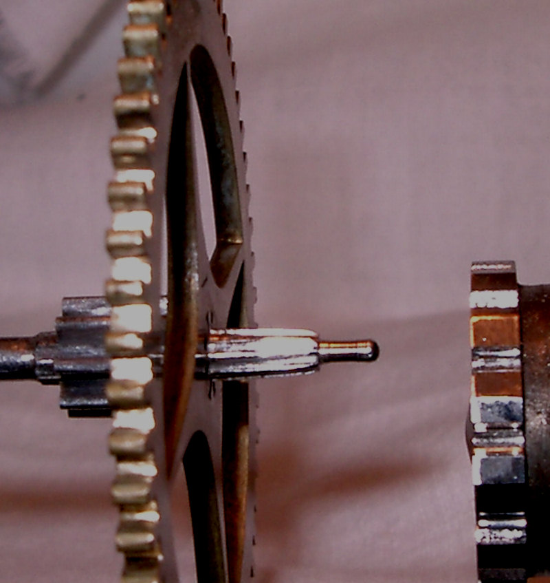 | ||||
|
| IHC President Life Member |
This is great John, wonderful images, an outstanding restoration story! Lindell | |||
|
| IHC Life Member Moderator |
What a professional job! Just very great and no apologies required anywhere. | |||
|
Lindell, Moses, Many many thanks for the kind words, really appreciated. There are still a few photo's to come yet, which I'll post with comments when I get them cropped etc. Some have been unuseable because the shine on the pivots turned them into a blur. Will have to spend more time playing with the camera settings methinks! Only wish some of my pocket watch 'resto' photo's came out as well. Many are quite unuseable, and many were lost when I trialled Adobe CS3 which changed all the file formats. Converting them back to .jpg's from .psp files ruined them for some reason. I've a few more of these projects to post when this one's done too, so watch this space! Best regards John | ||||
|
Very, very nice work John. You are true master!!!! IHC Member 1193 | ||||
|
Thank you for the kind comment Chris, and for having me realise I hadn't finished putting up more photo's - got the train wheels etc to show yet. Best regards John | ||||
|
A couple of 'before and after' train wheel a barrel photo's! Heavily sooted up and rusted steel parts (coal fires and damp conditions) took some cleaning up! John. Winding barrel before! (both barrels in the same state) 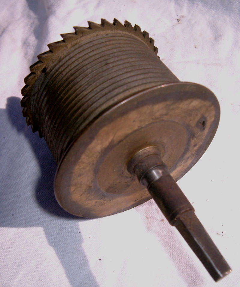 | ||||
|
Barrel after cleaning. JW. 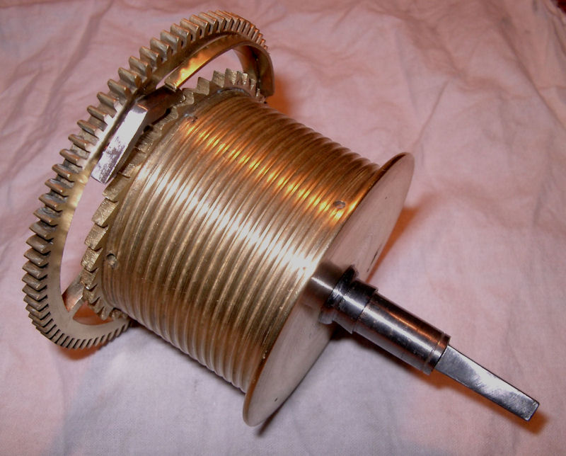 | ||||
|
Typical condition of all train wheels - time and strike! JW. 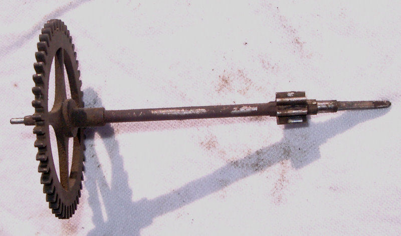 | ||||
|
Selection of wheels and arbors after cleaning up. JW. 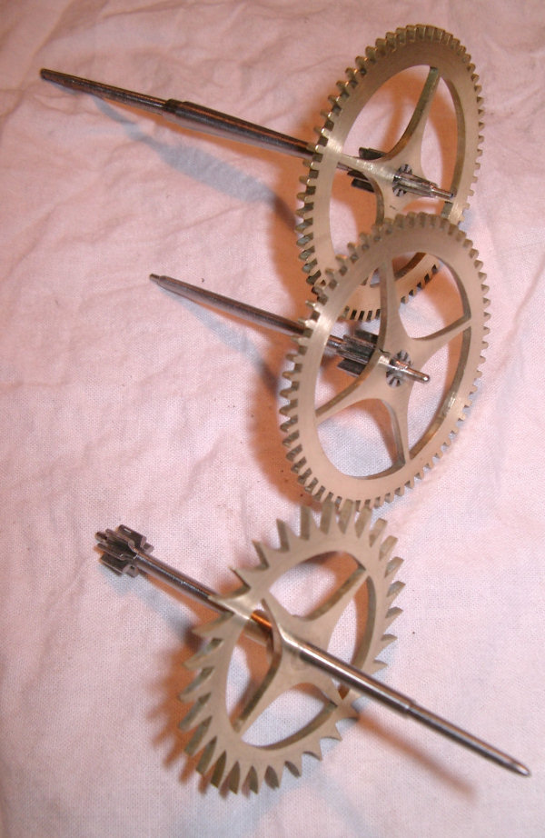 | ||||
|
The crutch foot was broken off and hanging loose on the pendulum. The original manufacture was by attaching the foot to the crutch rod by 'butt welding', which is about as weak a weld as you'll find anywhere! However, this is a mid C19th movement and things have moved on since then! Although replacement feet are available, I decided to repair the original using a 'mechanical' joint rather than weld or silver solder. The end of the crutch rod was filed into a round stump equal to the depth of the edge of the foot, and approx 0.7mm diameter, then the foot drilled to take the rod as a tight push fit. Final assembly was to 'loctite' the rod and foot together. Worked a treat, lined up beautifully and still going strong! JW. Broken crutch. 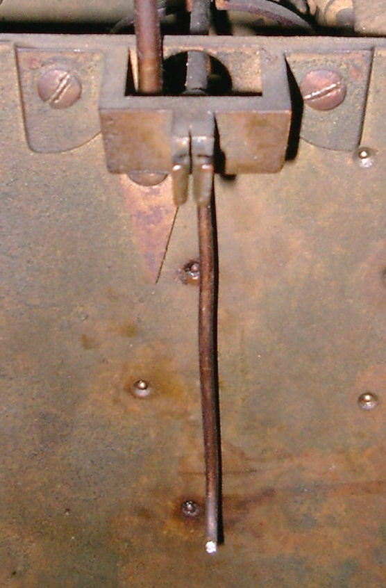 | ||||
|
Repaired crutch. JW. | ||||
|
| Powered by Social Strata |
| Your request is being processed... |
|
Welcome Aboard IHC185™  Internet Horology Club 185
  IHC185™ Discussion Site Main Page
  Horological Discussions, Questions and Answers
  Clocks, Including 400-Day Discussions
  S.Hart Devizes, Longcase Movement Restored.
 Internet Horology Club 185
  IHC185™ Discussion Site Main Page
  Horological Discussions, Questions and Answers
  Clocks, Including 400-Day Discussions
  S.Hart Devizes, Longcase Movement Restored.
©2002-2025 Internet Horology Club 185™ - Lindell V. Riddle President - All Rights Reserved Worldwide

